Light is one of those chapters where a student can read every definition and still feel uncertain when the blank page asks for a ray diagram. The confusion is understandable. A sentence tells you what light does; a diagram asks you to predict its path, preserve geometry, follow a sign convention and infer an image—all at once.
The way out is not to memorise twenty finished diagrams as pictures. Learn a small number of reliable ray rules, understand why they work, and construct each image from evidence. Once that habit settles, mirrors, lenses and numericals stop looking like separate topics and begin to feel like one connected story.
Start with the one distinction that organises the chapter
| Phenomenon | What happens | What remains central |
|---|---|---|
| Reflection | Light returns into the same medium after meeting a surface | The normal and the equality of the angles of incidence and reflection |
| Refraction | Light enters another medium and its direction may change because its speed changes | The normal, relative optical density and the change in speed |
Angles are measured from the normal, not from the mirror or boundary. This single detail causes a surprising number of errors. Draw the normal at the point where the ray meets the surface, then mark the incident and reflected or refracted angles.
Reflection: make the laws visible
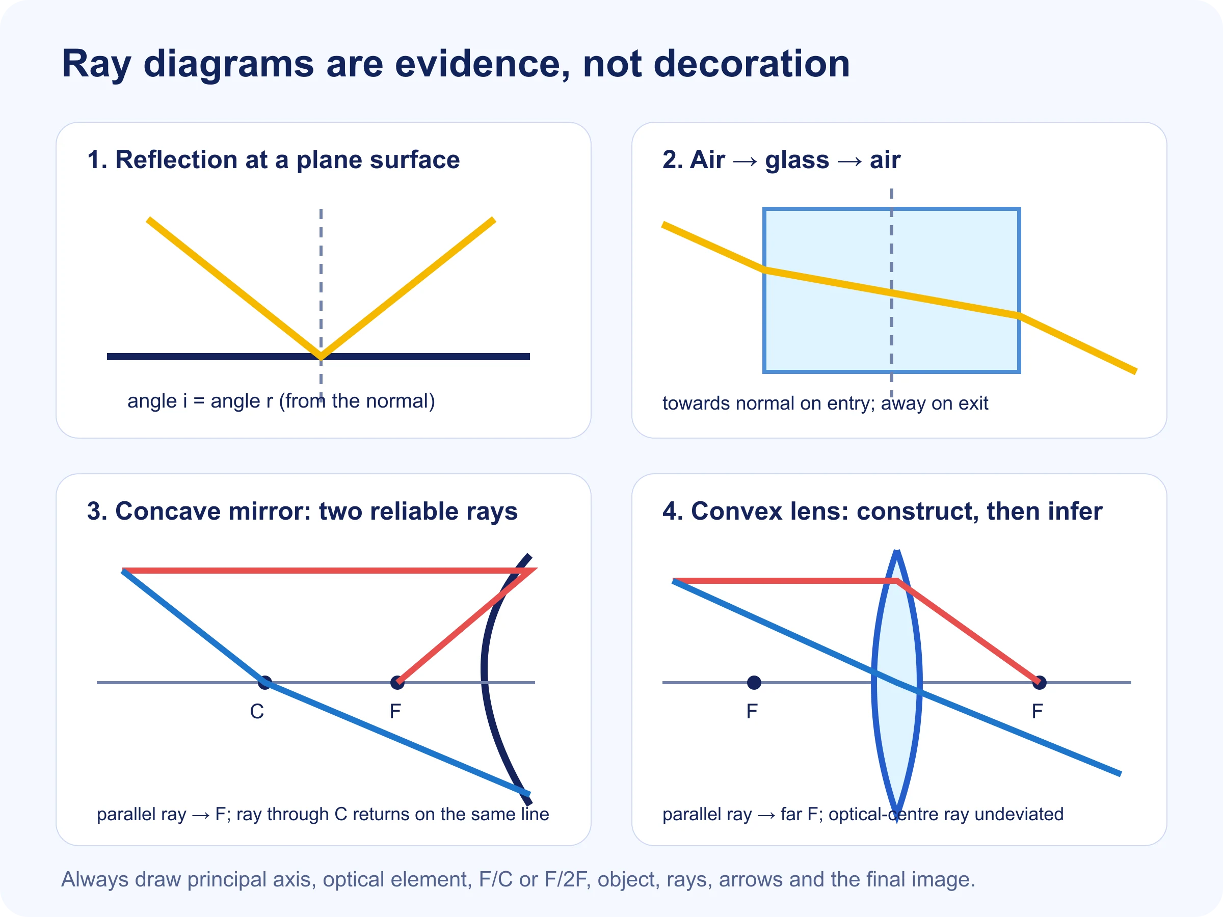
The incident ray, reflected ray and normal lie in one plane, and the angle of incidence equals the angle of reflection. Do not treat these as two lines to recite. In a diagram, they explain why the outgoing ray has a particular direction. If a question rotates the mirror, the normal rotates with it; the ray path must be rebuilt rather than copied from memory.
Spherical mirrors: understand the map before the images
- Pole (P): the geometric centre of the reflecting surface.
- Principal axis: the reference line passing through P and the centre of curvature.
- Centre of curvature (C): the centre of the sphere of which the mirror is a part.
- Principal focus (F): the point connected with rays parallel and close to the principal axis.
- Focal length: the distance PF; for a spherical mirror in the usual Class 10 treatment, the radius of curvature is approximately twice the focal length.
A concave mirror converges parallel rays in the real-focus situation. A convex mirror diverges them, and their backward extensions appear to meet behind the mirror. The word “behind” is not enough to decide a sign; the adopted Cartesian direction is what decides it.
The ray rules that replace diagram memorisation
For spherical mirrors
- A ray parallel to the principal axis reflects through F for a concave mirror; for a convex mirror it appears to come from F.
- A ray directed through F reflects parallel to the principal axis.
- A ray directed through C retraces its path because it meets the mirror along the normal.
- A ray striking the pole follows the law of reflection about the principal axis.
For thin lenses
- A ray parallel to the principal axis passes through the far focus of a convex lens; through a concave lens it diverges as if from the near focus.
- A ray through the optical centre travels approximately undeviated in the school-level thin-lens model.
- A ray directed through the appropriate focus emerges parallel to the principal axis.
Choose two rays whose paths you know with confidence. Where the actual rays meet, a real image forms; where only backward extensions meet, the image is virtual. Then describe position, size, orientation and nature. Do not announce “real and inverted” before construction has shown it.
A seven-step ray-diagram routine
- Draw the principal axis with a ruler.
- Draw and label the mirror or lens; mark P or O.
- Place F and C, or F and 2F, on the correct sides at meaningful relative distances.
- Place an upright object arrow at the position stated.
- Draw the first standard ray with direction arrows.
- Draw a second independent standard ray.
- Mark the image where rays meet; use dashed backward extensions for a virtual image, then state its characteristics.
Practise by changing only the object position. This helps you see how image behaviour changes continuously instead of learning each row of an image table in isolation.
Refraction: direction follows a change in speed
When light passes obliquely from a less optically dense medium to a more optically dense medium, it bends towards the normal; in the reverse movement it bends away. If it travels along the normal, its speed changes at the boundary but its direction does not. Therefore “refraction always means visible bending” is an unsafe statement.
Optical density in this context is not the same as ordinary mass density. Use the speed of light or refractive index relationship relevant to the question. For a rectangular glass slab, the ray bends at both parallel faces and the emergent ray is parallel to the incident ray in the standard setup, though laterally displaced.
Refractive index without formula fear
The absolute refractive index of a medium relates the speed of light in vacuum to its speed in that medium: n = c/v. A larger refractive index means light travels more slowly in that medium. In Snell's law form, the ratio involving sines of the measured angles is tied to the pair of media; keep the direction and definition used by your textbook clear rather than applying an inverted ratio from memory.
The New Cartesian sign convention
Place the pole of a mirror or optical centre of a lens at the origin. Take the direction of incident light as positive along the principal axis; the opposite direction is negative. Perpendicular heights above the axis are positive and below are negative. Apply the convention to every distance before substitution.
Mirror and lens formula thinking
For school-level spherical-mirror problems, the mirror formula connects object distance, image distance and focal length. The thin-lens formula uses the corresponding signed quantities under the adopted convention. Magnification connects image height with object height and also relates to distances in the form appropriate to a mirror or lens.
Before calculating, predict roughly: should the image be real or virtual, enlarged or diminished, and on which side? After calculating, compare the signs and size with that prediction. This catches a wrong focal-length sign faster than repeating the arithmetic.
Worked reasoning example: concave mirror
Suppose an object is placed beyond C. Without memorising the finished picture, use a parallel ray that reflects through F and a ray through C that retraces its path. They meet between C and F. The constructed image is therefore real, inverted and smaller than the object. The result follows from the rays; the table merely records it.
Worked reasoning example: convex lens
Place an object between F and 2F. A parallel ray refracts through the far F, while a ray through the optical centre continues undeviated. The rays meet beyond 2F, producing a real, inverted and enlarged image. Move the object closer to F and notice why the meeting point travels farther away. This movement builds intuition for the formula.
Common mistakes and what they reveal
| Mistake | Underlying gap | Repair |
|---|---|---|
| Angles measured from surface | Normal is not being used as reference | Draw normal before marking any angle |
| Ray bends the wrong way | Media transition not identified | Write less dense → more dense or reverse first |
| Virtual image made with solid rays | Actual rays and extensions confused | Use dashed backward extensions |
| Diagram copied but labels misplaced | Image table memorised without geometry | Construct from two rules on a blank axis |
| Correct formula, impossible answer | Signs inserted after calculation | Assign signs before substitution and predict result |
How CBSE and RBSE students should practise
Use the current prescribed textbook and syllabus for your board. Practise direct concepts, labelled ray diagrams, sign-convention numericals and questions that place optics inside cameras, mirrors, lenses or observations. The context can change while the governing rule remains familiar. CBSE publishes curriculum-aligned competency resources; RBSE students should pair the same concept work with the current RBSE syllabus and model-paper directions.
A six-day chapter plan
- Day 1: reflection laws, normal and mirror vocabulary.
- Day 2: concave and convex mirror ray rules; construct images from blank axes.
- Day 3: refraction, glass slab and refractive index.
- Day 4: convex and concave lens ray rules.
- Day 5: sign convention, formulas and mixed numericals.
- Day 6: one timed mixed set, error classification and redrawing every incorrect diagram.
Useful next resources
Open the Class 10 Science Notes hub for available textbook and notes links. For unfamiliar case or experiment questions, use the competency-based Science guide. If your answers lose marks despite correct understanding, work through the Science answer-writing guide.
Frequently asked questions
Should I memorise every ray diagram?
No. Memorise and understand the small set of standard ray rules, then construct the required image using two rays.
Why do my numerical signs keep changing?
Because direction matters. Draw a small axis, mark incident-light direction and assign every signed distance before using the formula.
Is a convex mirror image always real?
No. In the standard Class 10 treatment for a real object, a convex mirror forms a virtual, erect and diminished image behind the mirror.
Can refraction occur without a visible change in direction?
Yes. A ray entering along the normal can change speed without bending away from its original line.